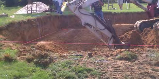
This picture shows the pool being dug so that there is a “shelf” to set the walls on, then the inward and downward direction of the dig. Note that the strings represent the wall location. For this pool, to the left you can see where most of the pool wall will be almost entirely in the ground while the other side (not shown) will be mostly out of the ground.
|
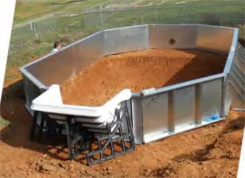
On ground pool with an outside step looks like when assembly is just about completed. Note most of the wall is out of the ground on the left hand side of this picture and the right hand side is half way in the ground (Not Shown).
|
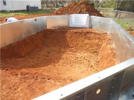
This is an On Ground pool dug with a “sports pool” bottom. Notice how the grades on the left and right hand side of the picture go inward and downward to achieve this “sports pool” finish. On both ends of the pool there are matching shallow end areas.
|
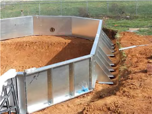
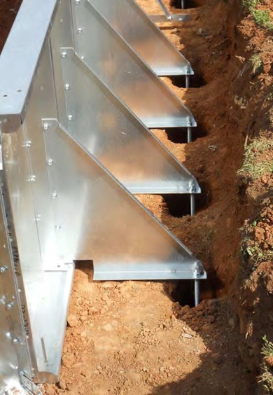
After the pool walls are assembled the side buttresses are put on the pool with J-bolts, as seen centered in the holes at the end of the buttress. These side buttresses prevent the pool from bowing outward on the long straight sides of the pool. The holes for the J-bolts to be anchored into should be at a minimum of 8” diameter and 4’ deep. A Sonotube can be used in these holes if preferred.
|
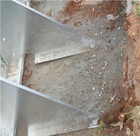
The 8” diameter 4’ deep holes have been filled with 4 – 80 lb. bags of concrete mix per hole, securing the J-bolt and pool wall system. This is done in place of pouring a concrete collar around the entire perimeter of the pool. Walls should be plumb and the pool dimensionally “square” prior to pouring these holes full of concrete.
|
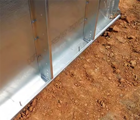
To help secure the pool prior to anchoring in the J-bolts, rebar pins are inserted through the bottom outside holes of the panels to keep the pool walls in a good general position. This helps when “squaring up” the pool.
|
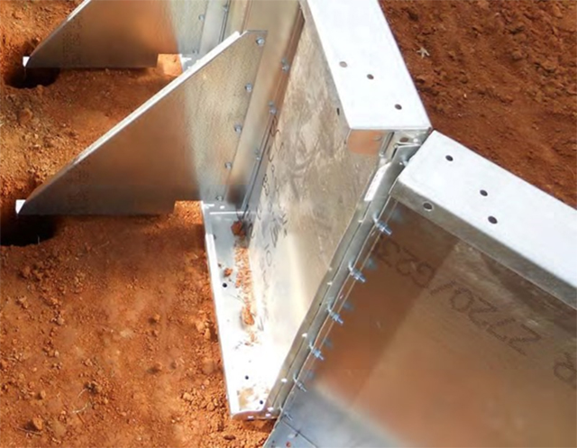
The On Ground Pool walls generally butt together and are bolted end to end. When there is a angled turn, an angle wedge bracket is used to join the two panel ends together as shown in the this picture.
|
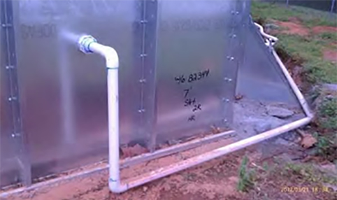
Plumbing on the pool can be done with schedule 40 rigid pvc pipe or schedule 40 flexible pvc pipe. We prefer to use “blue glue” which is a hotter glue and helps assure a good seal. Note the flexible pvc pipe in the background of this picture.
|
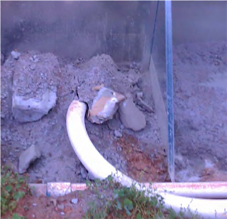
Here we used schedule 40 flexible pipe to go under the wall, down a trench and to the main drain’s location in the pool. The main drain is used to help circulate water from the deepest part of the pool through the filter system, ensuring better water filtration.
|
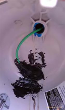
When a light is used, this is a close up view of the inside of the light niche. The green wire running in through the conduit at the back is secured to the niche; then covered with electrical potting compound
. |
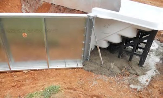
If a step is installed on the pool the entire step area including the braces should be encased in at least 6” of concrete as shown above. This was done using 80 lb bags of concrete mix purchased from the local hardware store.
|
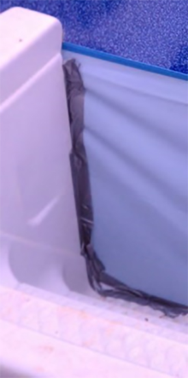
When the liner is installed a vacuum is pulled between the liner and the steel wall. Where the liner runs across the face of the step several strips of duct tape can help seal and close the gap so the liner can be “vacuumed out”. It is possible to use a standard shop vac or two to accomplish this. The important thing to remember is that once the liner is installed you should suck out as much air as possible from behind the liner, so that it will “lay down”.
|
|
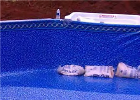
To help hold the liner across the face of the step the 50 lb bags of filter sand can be placed in the pool and pushed up against the step to help hold the liner in place and keep the duct tape from pulling off on the other side of the liner. Notice how the pulling the air out from behind the line has caused the liner to draw up close to the break line and in the bottom part of the pool walls. |